ThinkSystem SR650/SR630/SR550 -48 V DC Power Supply
The following publication is available in PDF format.
Note
You might need to download Adobe Acrobat Reader to view or print these documents. If so, go to the Adobe Reader download website.
ThinkSystem SR650/SR630/SR550 -48V DC Power Supply
The document provides necessary information of the option.
See this document for information about the ThinkSystem SR650/SR630/SR550 -48 V DC Power Supply.
This option kit comes with the following component.
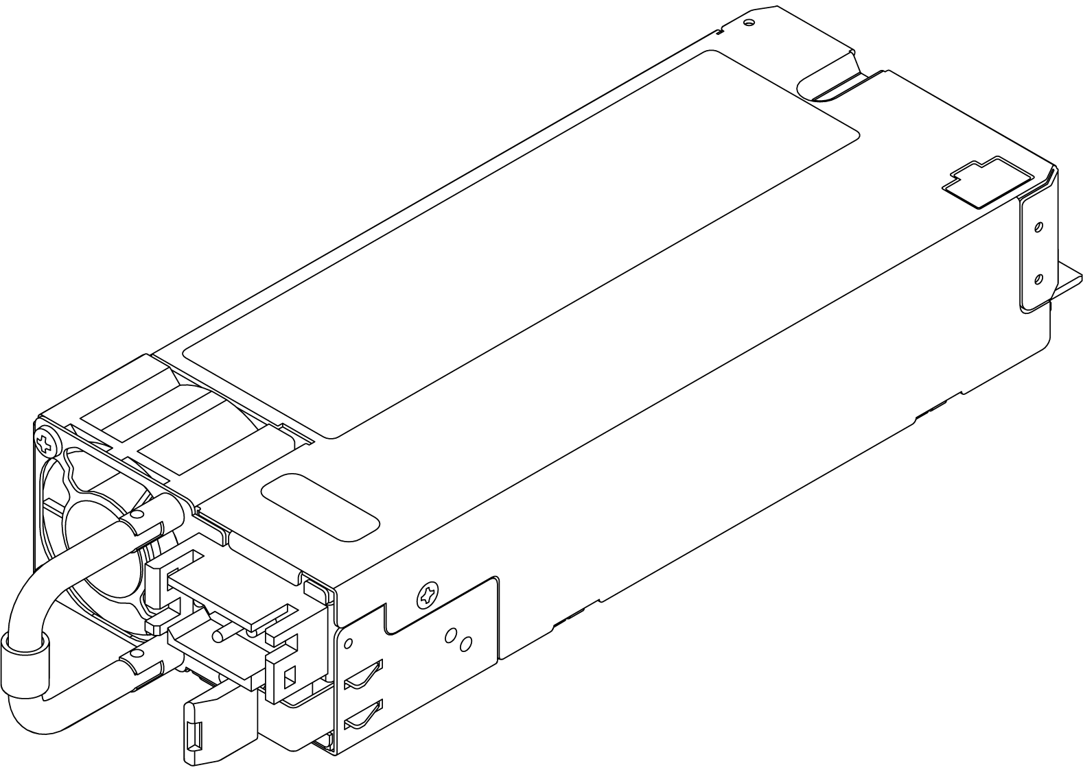
The following illustration shows the LEDs of the power supply.
LEDs of power supply

1 Power input LED
- Green: The power supply is connected to the DC power source.
- Off: The power supply is disconnected from the DC power source or a power problem occurs.
2 Power output LED
- Green: The server is on and the power supply is working normally.
- Blinking green: The power supply is in the zero-output mode (standby). When the server power load is low, one of the installed power supplies enters the standby state while the other one delivers the entire load. When the power load increases, the standby power supply will switch to the active state to provide sufficient power to the server.
To disable the zero-output mode, start the Setup utility, go to System Settings > Power > Zero Output, and select Disable. If you disable the zero-output mode, both power supplies will be in the active state.
- Off: The server is turned off, or the power supply is not working properly. If the server is turned on but the power output LED is off, replace the power supply.
3 Power supply error LED
- Yellow: The power supply has failed. To resolve the issue, replace the power supply.
- Off: The power supply is working normally.
NOTE
- This type of power supply is only powered by -48 V DC.
- This type of power supply can only be used on the SR650/SR630/SR550 servers.
- Before installing the power supply, user should confirm the technical feasibility with Lenovo.
Remove a hot-swap power supply
Use this information to remove a hot-swap power supply.

Read the installation Guidelines” in Chapter 3 of ThinkSystem SR650/SR630/SR550 Maintenance Manual.
ATTENTION: Static Sensitive Device Ground package before opening on Chapter 3 of ThinkSystem SR650/SR630/SR550 Maintenance Manual.
S035

CAUTION:
Never remove the cover on a power supply or any part that has this label attached. Hazardous voltage, current, and energy levels are present inside any component that has this label attached. There are no serviceable parts inside these components. If you suspect a problem with one of these parts, contact a service technician.
S002

CAUTION:
The power control button on the device and the power switch on the power supply do not turn off the electrical current that is supplied to the device. The device also might have more than one power cord. To remove all electrical current from the device, ensure that all power cords are disconnected from the power source.
S001

DANGER
Electrical current from power, telephone, and communication cables is hazardous.
To avoid a shock hazard:
- Do not connect or disconnect any cables or perform installation, maintenance, or reconfiguration of this product during an electrical storm.
- Connect all power cords to a properly wired and grounded electrical outlet.
- Connect to properly wired outlets any equipment that will be attached to this product.
- When possible, use one hand only to connect or disconnect signal cables.
- Never turn on any equipment when there is evidence of fire, water, or structural damage.
- Disconnect the attached power cords, telecommunications systems, networks, and modems before you open the device covers, unless instructed otherwise in the installation and configuration procedures.
- Connect and disconnect cables as described in the following table when installing, moving, or opening covers on this product or attached devices.
| To Connect: | To Disconnect: |
|---|---|
| 1. Turn everything OFF. | 1. Turn everything OFF. |
| 2. First, attach all cables to devices. | 2. First, remove power cords from outlet. |
| 3. Attach signal cables to connectors. | 3. Remove signal cables from connectors. |
| 4. Attach power cords to outlet. | 4. Remove all cables from devices. |
| 5. Turn device ON. |

Attention
This type of power supply is hot-swap only when two power supplies are installed for redundancy. If only one power supply is installed, you must turn off the server before removing the power supply. This power supply only supports some special configurations of the SR650/SR630/SR550 servers. For more information, consult the local Lenovo team.
在直流输入状态下,若电源供应器插座不支持热插拔功能,请务必不要对设备电源线进行热插拔,此操作可能导致设备损坏及数据丢失。因错误执行热插拔导致的设备故障或损坏,不属于保修范围。
NEVER CONNECT AND DISCONNECT THE POWER SUPPLY CABLE AND EQUIPMENT WHILE YOUR EQUIPMENT IS POWERED ON WITH DC SUPPLY (hot-plugging). Otherwise you may damage the equipment and result in data loss, the damages and losses result from incorrect operation of the equipment will not be covered by the manufacturers’ warranty.
S035
CAUTION:
Never remove the cover on a power supply or any part that has this label attached. Hazardous voltage, current, and energy levels are present inside any component that has this label attached. There are no serviceable parts inside these components. If you suspect a problem with one of these parts, contact a service technician.
S019
CAUTION:
The power-control button on the device does not turn off the electrical current supplied to the device. The device also might have more than one connection to dc power. To remove all electrical current from the device, ensure that all connections to dc power are disconnected at the dc power input terminals.
S029
DANGER
Electrical current from power, telephone, and communication cables is hazardous.
To avoid a shock hazard:
- Do not connect or disconnect any cables or perform installation, maintenance, or reconfiguration of this product during an electrical storm.
- Connect all power cords to a properly wired and grounded power source.
- Connect to properly wired power sources any equipment that will be attached to this product.
- When possible, use one hand only to connect or disconnect signal cables.
- Never turn on any equipment when there is evidence of fire, water, or structural damage.
- Disconnect the attached ac power cords, dc power sources, network connections, telecommunications systems, and serial cables before you open the device covers, unless you are instructed otherwise in the installation and configuration procedures.
- Connect and disconnect cables as described in the following table when you install, move, or open covers on this product or attached devices.
| To Connect: | To Disconnect: |
|---|---|
| 1. Turn OFF all power sources and equipment that is to be attached to this product. | 1. Turn OFF all power sources and equipment that is to be attached to this product. - For ac systems, remove all power cords from the chassis power receptacles or interrupt power at the ac power distribution unit. - For dc systems, disconnect dc power sources at the breaker panel or by turning off the power source. Then, remove the dc cables. |
| 2. Attach signal cables to the product. | 2. Remove the signal cables from the connectors. |
| 3. Attach power cords to the product. - For ac systems, use appliance inlets. - For dc systems, ensure correct polarity of -48 V dc connections: RTN is + and -48 V dc is -. Earth ground should use a two-hole lug for safety. | 3. Remove all cables from the devices. |
| 4. Attach signal cables to other devices. | |
| 5. Connect power cords to their sources. | |
| 6. Turn ON all the power sources. |
To remove a hot-swap power supply, complete the following steps:
Watch the procedure. A video of the removal process is available:
If the server is in a rack, adjust the cable management arm (CMA) to gain access to the power supply bay.
If you have installed the 2U CMA Upgrade Kit for Toolless Slide Rail or Toolless Slide Rail Kit with 2U CMA, do the following:

Press down the stop bracket 1 and rotate it to the open position.
Rotate the CMA out of the way to gain access to the power supply.
Disconnect the power cord from the hot-swap power supply.
Note: If you are replacing two power supplies, do the power supply replacement one by one to ensure that the power supply to the server is not interrupted. Do not disconnect the power cord from the secondly replaced power supply until the power output LED for the firstly replaced power supply is lit. For the location of the power output LED, refer to LEDs of Power Supply.
Press the release tab toward the handle and carefully pull the handle at the same time to slide the hot-swap power supply out of the chassis.
Note:
Slightly pull the power supply upwards when sliding the power supply out of the chassis, if you have installed one of the following CMA kits:
- 2U CMA Upgrade Kit for Toolless Slide Rail
- Toolless Slide Rail Kit with 2U CMA

After removing the hot-swap power supply:
Install a new power supply or install the power-supply filler to cover the power supply bay. For more information, refer to Install a hot-swap power supply.
Important: To ensure the proper cooling during the normal server operation, both of the power supply bays must be occupied. It means that each bay must have a power supply installed; or one has a power supply installed and the other has a power supply filler installed.
If you are instructed to return the old hot-swap power supply, follow all packaging instructions and use any packaging materials that are provided.
Install a hot-swap power supply
Use this information to install a hot-swap power supply.
Read the installation Guidelines” in Chapter 3 of ThinkSystem SR650/SR630/SR550 Maintenance Manual.
ATTENTION: Static Sensitive Device Ground package before opening on Chapter 3 of ThinkSystem SR650/SR630/SR550 Maintenance Manual.
The following tips describe the type of power supply that the server supports and other information that you must consider when you install a power supply:
- The standard shipping has only one power supply installed in the server. For redundancy and hot-swap support, you must install an additional hot-swap power supply. Certain customized models might be shipped with two power supplies installed.
- Ensure that the devices that you are installing are supported. For a list of supported optional devices for the server, go to: http://www.lenovo.com/us/en/serverproven/
NOTE
- Ensure that the two power supplies installed on the server have the same wattage.
- If you are replacing the existing power supply with a new power supply of different wattage, attach the power information label that comes with this option onto the existing label near the power supply.
S035
CAUTION:
Never remove the cover on a power supply or any part that has this label attached. Hazardous voltage, current, and energy levels are present inside any component that has this label attached. There are no serviceable parts inside these components. If you suspect a problem with one of these parts, contact a service technician.
S002
CAUTION:
The power control button on the device and the power switch on the power supply do not turn off the electrical current that is supplied to the device. The device also might have more than one power cord. To remove all electrical current from the device, ensure that all power cords are disconnected from the power source.
S001
DANGER
Electrical current from power, telephone, and communication cables is hazardous.
To avoid a shock hazard:
- Do not connect or disconnect any cables or perform installation, maintenance, or reconfiguration of this product during an electrical storm.
- Connect all power cords to a properly wired and grounded electrical outlet.
- Connect to properly wired outlets any equipment that will be attached to this product.
- When possible, use one hand only to connect or disconnect signal cables.
- Never turn on any equipment when there is evidence of fire, water, or structural damage.
- Disconnect the attached power cords, telecommunications systems, networks, and modems before you open the device covers, unless instructed otherwise in the installation and configuration procedures.
- Connect and disconnect cables as described in the following table when installing, moving, or opening covers on this product or attached devices.
| To Connect: | To Disconnect: |
|---|---|
| 1. Turn everything OFF. | 1. Turn everything OFF. |
| 2. First, attach all cables to devices. | 2. First, remove power cords from outlet. |
| 3. Attach signal cables to connectors. | 3. Remove signal cables from connectors. |
| 4. Attach power cords to outlet. | 4. Remove all cables from devices. |
| 5. Turn device ON. |
在直流输入状态下,若电源供应器插座不支持热插拔功能,请务必不要对设备电源线进行热插拔,此操作可能导致设备损坏及数据丢失。因错误执行热插拔导致的设备故障或损坏,不属于保修范围。
NEVER CONNECT AND DISCONNECT THE POWER SUPPLY CABLE AND EQUIPMENT WHILE YOUR EQUIPMENT IS POWERED ON WITH DC SUPPLY (hot-plugging). Otherwise you may damage the equipment and result in data loss, the damages and losses result from incorrect operation of the equipment will not be covered by the manufacturers’ warranty.
S035
CAUTION:
Never remove the cover on a power supply or any part that has this label attached. Hazardous voltage, current, and energy levels are present inside any component that has this label attached. There are no serviceable parts inside these components. If you suspect a problem with one of these parts, contact a service technician.
S019
CAUTION:
The power-control button on the device does not turn off the electrical current supplied to the device. The device also might have more than one connection to dc power. To remove all electrical current from the device, ensure that all connections to dc power are disconnected at the dc power input terminals.
S029
DANGER
Electrical current from power, telephone, and communication cables is hazardous.
To avoid a shock hazard:
- Do not connect or disconnect any cables or perform installation, maintenance, or reconfiguration of this product during an electrical storm.
- Connect all power cords to a properly wired and grounded power source.
- Connect to properly wired power sources any equipment that will be attached to this product.
- When possible, use one hand only to connect or disconnect signal cables.
- Never turn on any equipment when there is evidence of fire, water, or structural damage.
- Disconnect the attached ac power cords, dc power sources, network connections, telecommunications systems, and serial cables before you open the device covers, unless you are instructed otherwise in the installation and configuration procedures.
- Connect and disconnect cables as described in the following table when you install, move, or open covers on this product or attached devices.
| To Connect: | To Disconnect: |
|---|---|
| 1. Turn OFF all power sources and equipment that is to be attached to this product. | 1. Turn OFF all power sources and equipment that is to be attached to this product. - For ac systems, remove all power cords from the chassis power receptacles or interrupt power at the ac power distribution unit. - For dc systems, disconnect dc power sources at the breaker panel or by turning off the power source. Then, remove the dc cables. |
| 2. Attach signal cables to the product. | 2. Remove the signal cables from the connectors. |
| 3. Attach power cords to the product. - For ac systems, use appliance inlets. - For dc systems, ensure correct polarity of -48 V dc connections: RTN is + and -48 V dc is -. Earth ground should use a two-hole lug for safety. | 3. Remove all cables from the devices. |
| 4. Attach signal cables to other devices. | |
| 5. Connect power cords to their sources. | |
| 6. Turn ON all the power sources. |
Before installing a hot-swap power supply, touch the static-protective package that contains the new hot-swap power supply to any unpainted surface on the outside of the server. Then, take the new hot-swap power supply out of the package and place it on a static-protective surface.
To install a hot-swap power supply, complete the following steps:
Watch the procedure. A video of the installation process is available:
If the server is in a rack, adjust the cable management arm (CMA) to gain access to the power supply bay.
If you have installed the 2U CMA Upgrade Kit for Toolless Slide Rail or Toolless Slide Rail Kit with 2U CMA, do the following:
Press down the stop bracket 1 and rotate it to the open position.
Rotate the CMA out of the way to gain access to the power supply bay.
Note the orientation and slide a power-supply filler is installed, remove it.

Slide the new hot-swap power supply into the bay until it snaps into position.

After installing the hot-swap power supply:
- Connect one end of the power cord to the new power supply connector; then, connect the other end of the power cord to a properly grounded electrical outlet.
- If the server is turned off, turn on the server. Ensure that both power input LED and the power output LED on the power supply are lit, indicating that the power supply is operating properly. For the location of the power supply LEDs, refer to refer to LEDs of Power Supply.
Option installation
- To install the option, refer to:
- For the latest technical information including firmware and driver downloads, go to Lenovo Data Center Support.
| Option installation | |
|---|---|
| To install the option, refer to “Hardware replacement procedures” in the server User Guide, which is available at Lenovo Docs https://pubs.lenovo.com. | |
| For the latest technical information including firmware and driver downloads, go to Lenovo Data Center Support website https://datacentersupport.lenovo.com. | |
First Edition (May 2021)
© Copyright Lenovo 2021.
LIMITED AND RESTRICTED RIGHTS NOTICE: If data or software is delivered pursuant to a General Services Administration (GSA) contract, use, reproduction, or disclosure is subject to restrictions set forth in Contract No. GS-35F-05925