ThinkSystem SR650 U.2 24-Bay Upgrade Kit
This document provides important information about ThinkSystem SR650 U.2 24-bay Upgrade Kit. This upgrade kit is provided to upgrade the 24-bay server model to the server model with twenty-four 2.5-inch NVMe drives. Store the documentation for future reference.
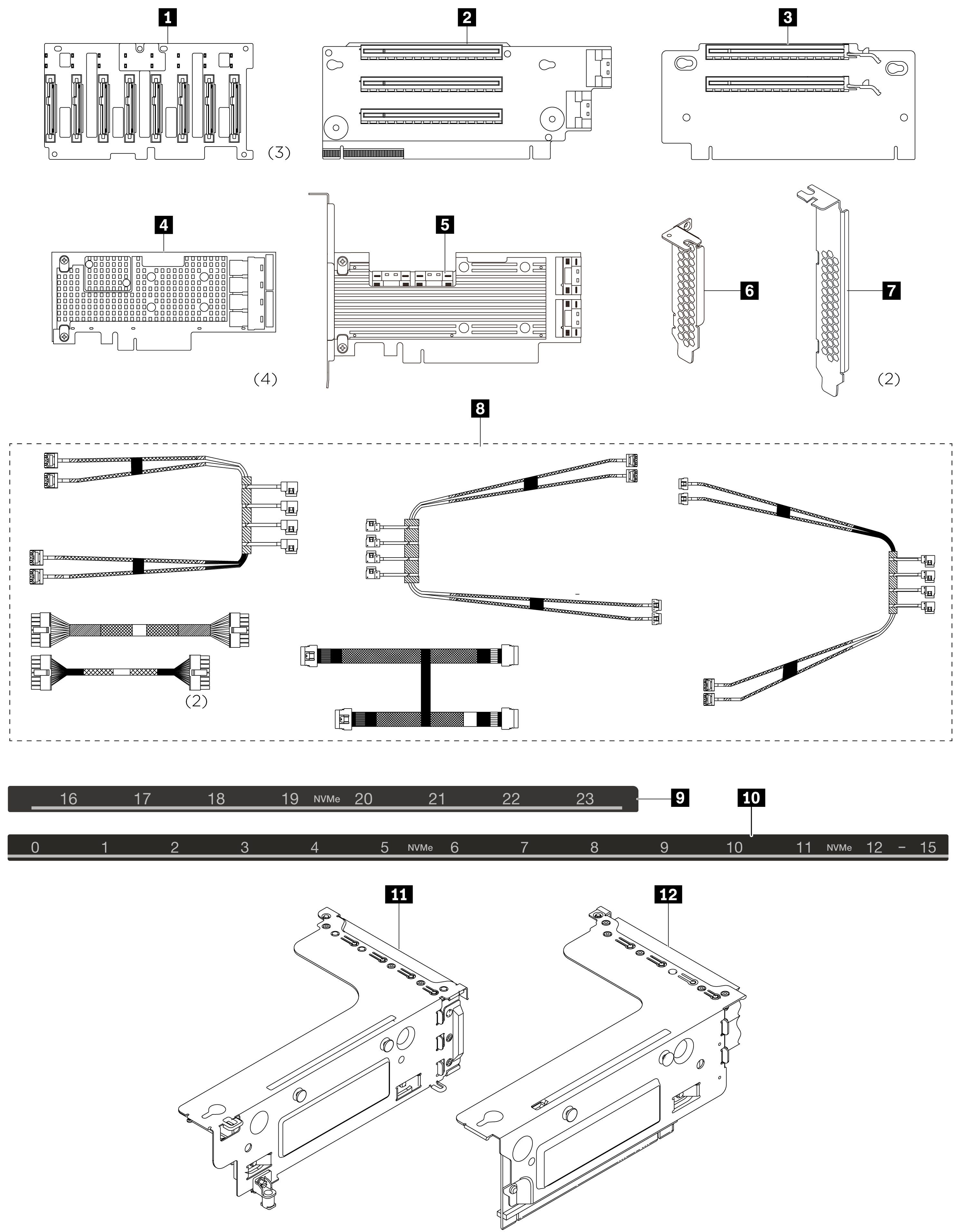
The option package contains the following items:

1 ThinkSystem SR650 2.5-inch NVMe 8-Bay backplane (3)
2 ThinkSystem SR650 x16/x8/x16 PCIe riser card 1
3 ThinkSystem SR550/SR650 x16/x16 PCIe riser card 2
4 ThinkSystem 810-4P NVMe switch adapter (4)
5 ThinkSystem 1610-8P NVMe switch adapter
6 2U bracket for PCIe switch adapter
7 3U bracket for PCIe switch adapter (2)
8 ThinkSystem SR650 24 NVMe config cable kit
9 Sequence label (16–23 NVMe)
10 Sequence label (0–15 NVMe)
11 Riser 1 bracket
12 Riser 2 bracket
The following information is a summary of the PCIe switch adapters and the corresponding PCIe slots. For information about PCIe slot location, refer to Rear view in the ThinkSystem SR650 Maintenance Manual.
| PCIe switch adapter type | PCIe slot selection |
|---|
|
4 810-4P NVMe switch adapter (with the 3U bracket 7 installed)|Slot 2 on riser card 1|
|
4 810-4P NVMe switch adapter (with the 2U bracket 6 installed)|Slot 4 on the system board|
|
4 810-4P NVMe switch adapter (with the 3U bracket 7 installed)|Slot 6 on riser card 2|
|
4 810-4P NVMe switch adapter|RAID adapter slot on the system board|
|
5 1610-8P NVMe switch adapter|Slot 1 on riser card 1|
Attention
Before installing components in your server, read Installation Guidelines in the ThinkSystem SR650 Maintenance Manual.
To complete the setup with the upgrade kit, do the following:
Watch the procedure. A video of the installation process is available:
- Youtube: https://www.youtube.com/playlist?list=PLYV5R7hVcs-A25P7vBoGa_wn7D7XTgDS_
- Youku: http://list.youku.com/albumlist/show/id_50483444
- Remove any required hardware or server options before you use this upgrade kit. For information about how to remove or install the required hardware or server options, see Hardware replacement procedures in the ThinkSystem SR650 Maintenance Manual.
- Install the three 2.5-inch NVMe 8-Bay backplanes 1. See Install the 2.5-inch-drive backplane. Then, apply drive bay sequence labels 9 10 above the drive bays on your server.
- Install three brackets on three 810-4P NVMe switch adapters. To install the bracket, align the screw holes in the bracket with the corresponding holes in the switch adapter, and then, install the screws to secure the bracket to the switch adapter.
- Install the 810-4P NVMe switch adapter 4 in the RAID adapter slot on the system board. See Install the RAID adapter.
- Install the 810-4P NVMe switch adapter 4 with 2U bracket 6 in PCIe slot 4 on the system board. See Install a PCIe adapter on the system board.
- Install the riser card 1 2 on riser 1 bracket. See Install a riser card.
- Install the 1610-8P NVMe switch adapter 5 in PCIe slot 1 on riser card 1. Then, install the 810-4P NVMe switch adapter 4 with 3U bracket 7 in PCIe slot 2 on riser card 1. See Install a PCIe adapter on the riser assembly.
- Install the riser 1 assembly to the chassis. See Install a riser card.
- Install the riser card 2 3 on riser 2 bracket. See Install a riser card.
- Install the 810-4P NVMe switch adapter 4 with 3U bracket 7 in PCIe slot 6 on riser card 2. See Install a PCIe adapter on the riser assembly.
- Install the riser 2 assembly to the chassis. See Install a riser card.
- Install any required hardware or server options, and then cable the server. To connect cables for server models with twenty-four NVMe drives, see “Server model: twenty-four 2.5-inch NVMe drives, four NVMe 810-4P switch adapters, one NVMe 1610-8P switch adapter” in the topic Server models with twenty-four 2.5-inch drives.
The most up-to-date ThinkSystem SR650 Maintenance Manual is always available for download at: https://thinksystem.lenovofiles.com/help/index.jsp
To get the latest technical information and download device drivers and updates, go to: https://www.lenovo.com/support